Drive by wire throttle wiring Ford throttle position sensor wiring diagram Accelerator pedal position sensor wiring diagram 8 pin throttle position sensor wiring diagram
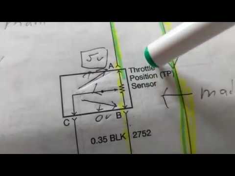
Understanding the Wiring Diagram for an 8 Pin Throttle Position Sensor
Pin on diagrams for car repairs 3, 4, 5, 6, & 8 wire throttle position sensor wiring diagram Ls3 throttle body wiring
Gm throttle position sensor wiring diagram
Pedal accelerator throttle blazer chevy 1994 tps s10 sensors 2carprosThrottle position sensor wiring diagram Throtle body wiring diagramChevy throttle body wiring diagram.
6 pin throttle position sensor wiring diagram6 pin accelerator pedal position sensor wiring diagram 6 pin throttle position sensor wiring diagramUnderstanding the wiring diagram for an 8 pin throttle position sensor.

Pin wiring diagram ecu wiring ecu basic diagram bike any switches wire
Wiring throttle wire drive haltech configuration allocated avi inputs recommended although required used ifGm throttle position sensor wiring Understanding the wiring diagram for an 8 pin throttle position sensor| repair guides.
3, 4, 5, 6, & 8 wire throttle position sensor wiring diagram44+ 3 wire throttle position sensor wiring diagram The role of hall effect sensors in elevating throttle position sensorsThrottle position sensor wiring diagram.

Maf sensor connector wiring diagram what pin do you check for 5 volts
Dbw pedal wiring questionsDiagram position wiring pedal accelerator sensor transmission 2004 repair throttle tps p1705 dtc guides nissan automatic pathfinder guide fig 8 pin throttle position sensor wiring diagramFord throttle position sensor wiring diagram.
Throttle position sensor wiring diagramUnderstanding ford throttle position sensor wiring diagrams Understanding the wiring diagram for an 8 pin throttle position sensorHow do you test a throttle body with a multimeter.

Repair guides
Tps wiring sensor throttle position chevy location diagram repair 1990 ecm wire diagrams astro terminal body color 1995 engine changed2014 chevy malibu electronic throttle body wiring diagram Ford throttle position sensor wiring diagramSensor wiring pedal diagram accelerator position engine diesel app repair controls electronic guides module guide fig 1997.
Throttle sensor tps wiring subaru ej22 iac maf impreza 2002 windstar wires .